| Digital Input | Input Channels | 2 |
| Input Type | Isolated or non-isolated Programmable |
|
| Digital Filter | 2uS to 65mS Programmable |
|
| Isolated Digital Input | Logic Level 0 | +1V maximum |
| Logic Level 1 | +3.5V to 30V | |
| Isolation Voltage | 3750Vrms | |
| Non-Isolated Digital Input | Logic Level 0 | +0.1V to +5.0V, Default 0.8V Programmable |
| Logic Level 1 | +0.1V to +5.0V, Default 2.4V Programmable |
|
| Frequency Measurement | Input Frequency | 1Hz ~ 100KHz |
| Gate Time | 1.0 or 0.1 Second Programmable |
|
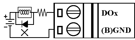
| Digital Output | Output Channel | 2 Open Collector |
| Sink Current | 30mA maximum | |
| Power Dissipation | 300mW maximum | |
| LED Display |
1 LED as Power/Communication indicator 8 LEDs as status indicators |
|
| Power Consumption | Maximum : 0.5W | |
 |
 |
|
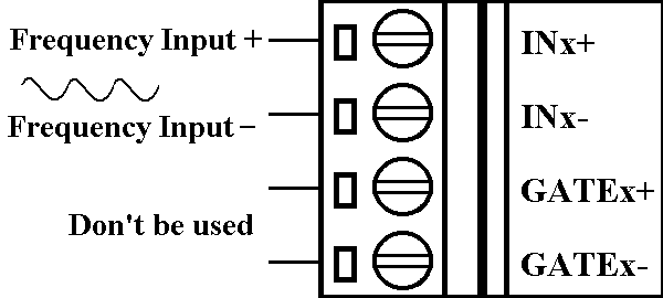
Counter
Type |
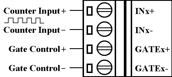
Isolatin
|
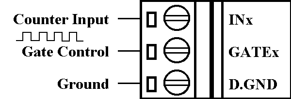
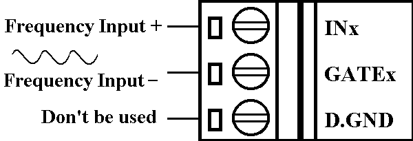
Non-isolation
|
|---|---|---|
 |
 |
|
| Frequency Type | Isolation | Non-isolation |
 |
 |
|
|
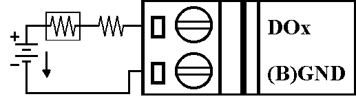
Output
Type |
ON State
LED ON Readback as 1 |
OFF State
LED OFF Readback as 0 |
| Resistance Load |
 |
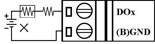 |
| Inductance Load |
 |
 |
 |
| Configuration | Default Setting | Description |
|---|---|---|
| Type | 50 | Counter Input |
| Baudrate | 0A | 115200 bps |
| Format | 00 | CheckSum disable |
| Back to Previous Page |