| Analog Input | Input Channel | 8 differential input channels | |
| Input Type |
|
||
| Sampling Rate | 100K sample rate for single channel in polling mode, 50K sample rate for single channel in interrupt mode, 10K sample rate for 8 channels scan in interrupt mode. |
||
| Accuracy | +/-0.1% | ||
| Common Mode Rejection | typic 86dB | ||
| Voltage Input Impedance | 20K/200K/20M Ohms (Jumper Select) 200K(Default) ( Note 1) |
||
| Overvoltage Protection | -35V to +35V maximum | ||
| Isolation Voltage | 3000Vrms | ||
| LED Display |
1 LED as Power indicator 16 LEDs as High/Low Alarm signals |
||
| Power Requirement | DC +5V, 480mA maximum | ||
| Jumper position | |
Input impedance setting jumper Default : 200K Ohm Both of them should set on the same value, and input impedance = 2 * setting value |
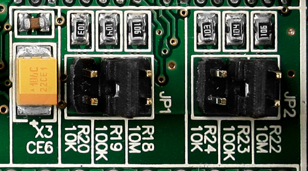 |
Note 1: I-8017H module has Input impedance setting jumper on the PCB board Version 5.6 or later .
The PCB board Version before 5.5 doesn't have the Jumper ,it only can use inside Default value : 200K Ohm
| Back to Previous Page |